















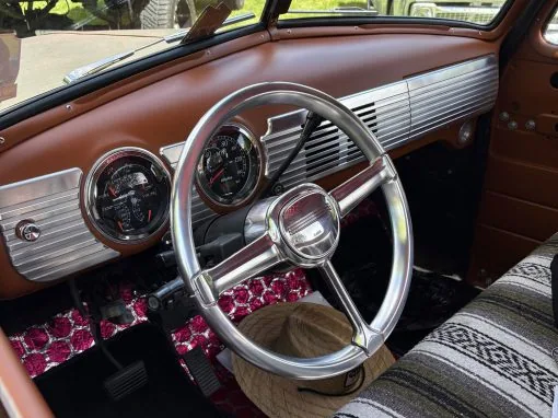

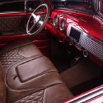

The full billet dash for a 1947-53 Chevy truck comes in two parts. The speaker grille and glove box set goes in first, and the Phantom dash pieces follow it. Both are CNC machined from 6061 billet aluminum. These instructions will help you fit your new billet speaker grille and glove box for a perfect fit and finish. There’s a slight difference from one truck to another. However, with some patience and our photos as reference, you’ll have your new billet dash pieces installed in minimal time.
Billet dash speaker grille and glove box install
Installing Supplied Hardware
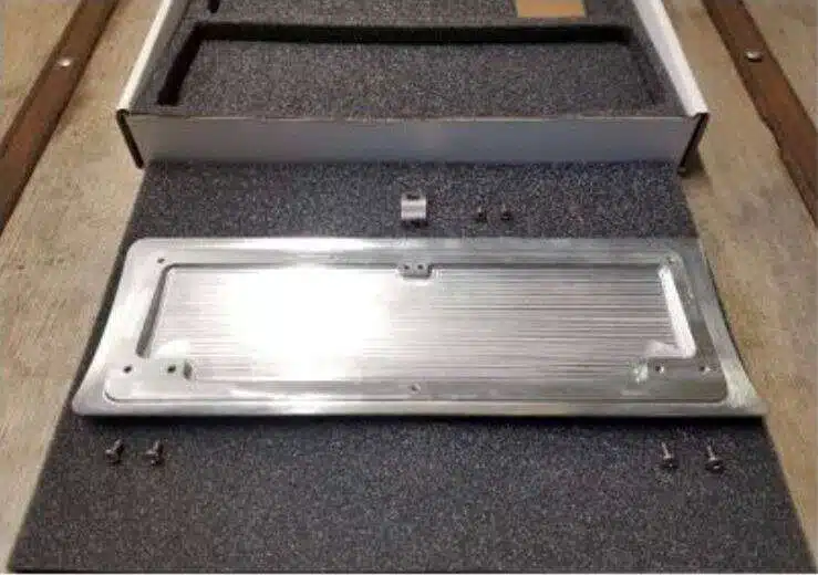
After opening the box, remove the speaker grille from the packaging and flip it over onto the packaging foam to view the backside. Remove the hardware from the bag located behind the speaker grille and thread in the supplied Allen keys (4) #8 stainless steel studs into the four corners of the speaker grille. Blue Loctite can be applied but isn’t required. Retrieve the (4) #8 stainless steel lock nuts.
Remove the bottom glove box door and flip it over onto a cloth or soft surface to view the backside. Remove the (2) #10 ¼″ stainless pan head screws and fasten the LS stainless steel latch. Also remove the (4) stainless steel #8 3/8″ pan head screws to be used for attaching the hinges.
Speaker Grille Install
Install the billet speaker grille into the original holes — the studs slide into existing holes. Be careful not to scratch your dash. Reach behind and thread on the (4) supplied #8 nuts finger tight. There’s some adjustment available, but wait until the glove box is on to see what’s needed.
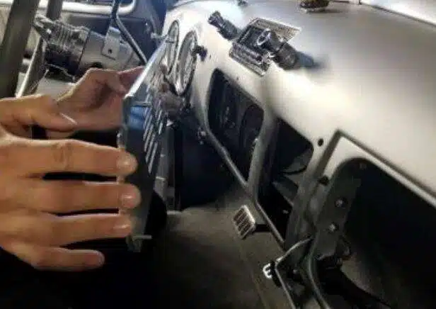
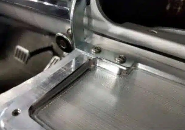
Be very careful closing the glove box door — watch for any rubbing and watch the top of the latch.
- Mount the hinges. Hold the glove box door open (on your knees if sitting on the seat) and swing the hinges toward the mounting holes. With a Phillips screwdriver, gently thread in the #8 3/8″ stainless screws. Start with the glove box as low as possible before tightening.
- Test the close. Slowly and carefully close the door, inspecting all painted surfaces — nothing should bind, rub, or touch the dash surfaces. Adjust the hinge up/down, left/right, or in/out if needed. Inspect latch clearance as you close — the stainless latch comes very close and might need door adjustment to clear the top of the dash.

Image 5 - Align the grille. Once the door closes without binding or rubbing, align the speaker grille to be level with the glove box — move it up/down, left/right for an almost seamless look. There are 8 screws total to adjust glove box placement. After each adjustment, carefully close the glove box again and watch for rubbing or misalignment. Once alignment is right, tighten all hardware and remove fingerprints or tape.

Image 6 
Image 7
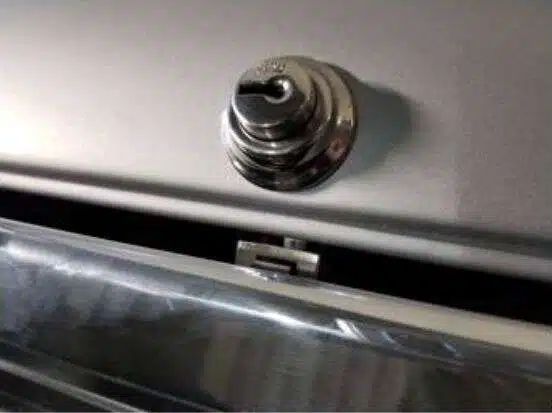
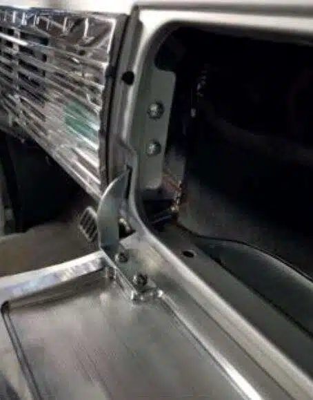
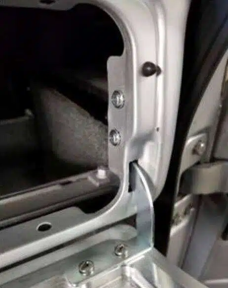
Your dash is now installed! Continue below for instructions on installing the extended full dash (Phantom Dash).
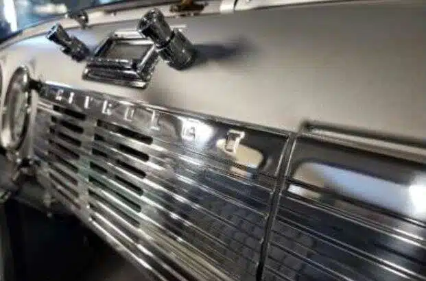
Phantom dash install for the full billet dash
The Phantom pieces finish the full billet dash by carrying the machined face across to the driver side.
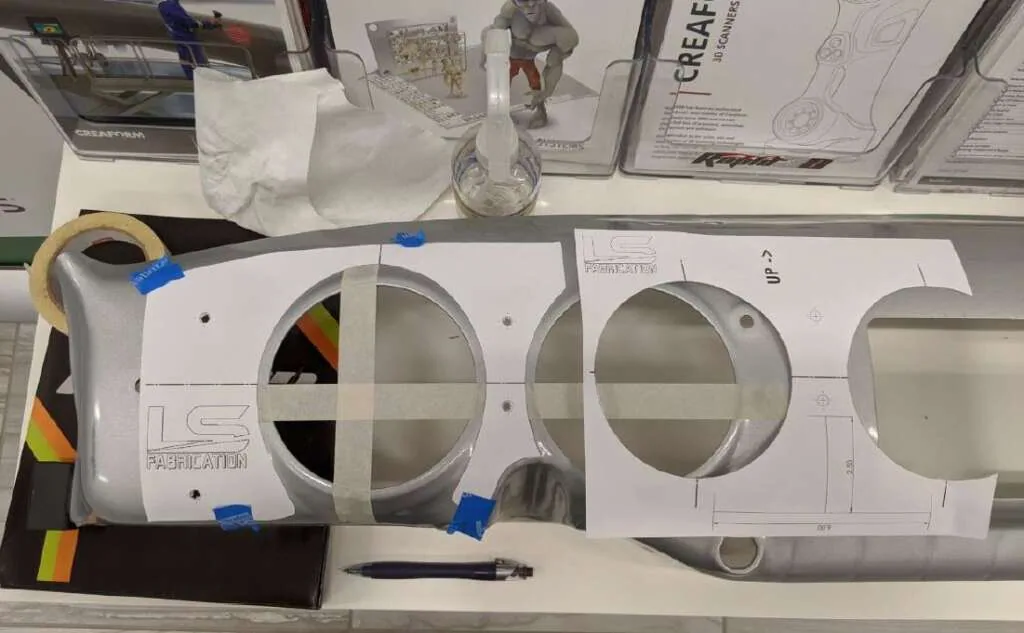
These instructions will help you fit your new Phantom Billet Dash pieces for a perfect fit and finish. Take your time and use the images as reference. Use the supplied installation templates below:
Installing Supplied Hardware
Both Phantom Gauge pieces come with (2) 1″ #8 set screws and (2) flange nuts. Use the supplied Allen key to install the set screws into the back of the Phantom Dash pieces. The gauge piece needs a set screw in the top and middle, while the piece around the light switch needs set screws in the top and bottom. Blue Loctite can be applied but isn’t required.
Billet dash installation templates
- First, verify the print size. Measure the 4″ and 6″ scale lines to confirm the print size is correct.
- Then cut out the templates. Carefully cut out installation Template 1 and Template 2.
- Finally, use Template 1, then Template 2.
Template 1
The first sheet, Template 1, places a masking tape crosshair on the left gauge so the second sheet aligns perfectly:
- First, align the gauge circle cutouts to the gauge holes.
- Then use a small piece of tape to hold it in place.
- Make horizontal and vertical “crosshairs” through the left gauge — don’t curve the tape, make pieces longer than needed and rip right at the bottom.
- Verify your crosshair lines are centered — should be ~2.6″ to center for both.
- You can leave the template on or remove it and just leave the tape.
Template 2
After that, Template 2 determines hole placement for the Phantom Dash pieces:
- First, attach a small piece of tape to hold the paper and allow adjustment.
- Next, align the vertical and horizontal lines perfectly to the tape crosshairs.
- With the set screws in, confirm the Phantom Dash pieces sit correctly.
- Then drill the holes, starting with a ¼″ bit. Work up in size and keep checking fitment, but don’t go larger than 3/8″. On a finished truck, the steering column may need to drop slightly to drill the bottom center hole.
- Once holes are complete, use a Q-tip to apply a little paint or copper coat if the dash was already painted.
- Finally, install the Phantom Dash pieces using the supplied #8 flange nuts. Verify the final placement before fully tightening.
If you only bought the grille and glove box, the shorter grille and glove box guide covers just that half. The double din version of the dash installs the same way. The billet dash pieces sit alongside our AC and heater vents, cup holders and speaker brackets cut for the same dash — all in the 47-54 truck parts collection.
Full billet dash: tips from our shop
- First, unpack every piece and lay it out before you touch the dash, so you know what is in the box.
- Also, keep the protective film on the machined faces until the very last step.
- Then work with the glove box hung but loose, because the grille aligns to it rather than the other way round.
- However, do not force a screw. If a hole does not line up, back the hardware off and shift the piece.
- In addition, a drop column makes the Phantom pieces far easier to fit on a finished truck.
- Finally, clean the aluminium with a soft cloth only, since anything abrasive dulls the machined finish.
For any questions or concerns with your install, don’t hesitate to email us at info@lsfab.com
Printable instructions
Pick the sheet that matches your truck. They print on letter paper.
0 Comments